First use
This section will introduce you to the software display and basic operating information of the Medusa 96. Newbies must read this chapter.
On/off pipette
After plugging in the power cord, turn the switch next to the outlet to the ON state. The device is not yet ready to start.
Turn the black switch located at the bottom right of the device to the ON position. The device will now power up.
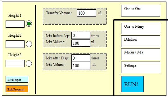
After the two startup pages are displayed one after another, the device's operation interface will be displayed:


Software launch page
If you want to quit the software, just click the “Exit Program†button in the lower left corner with the pen, the shutdown screen will be displayed: 
Shutdown interface At this time, you can turn off the black switch at the bottom right of the device to the OFF position.
Use of moving parts and disk placement
The pipette has a mechanical platform for XYZ three-dimensional mobile positioning. The definition of the three axes and how to move:
X axis: left and right direction, by the right hand holding the operating handle, the force is applied to the left and right, and there are positioning grooves at both ends;
Y-axis: in the front-rear direction, the moving frame on the working surface is pulled out, and the inside position will face the pipetting head;
Z-axis: In the vertical direction, the motion is manipulated by pressing a button on the operating handle, and the 2 button is up 3 buttons.
        Medusa 96 has taken into account the situation that users may encounter when using it. It has been set that the Z axis must move up and down after the pipetting head has been moved or the working disk surface has reached the set position . Prevent the occurrence of misplacement of the pipetting head and the position of the pan.
There are 4 bays in the front and rear slots on each moving frame. The size of the disk is just enough to accommodate the SBS standard 96-well plate, including the full-length ELISA plate, cell culture plate, PCR plate, and various solution tanks.
The size of the tip box is also SBS compliant and can be placed directly on the tray. Note the direction in which the Tips rack is placed, and the notched side should be on the left side. This tip box is common to both 1000 ul and 200 ul.
The 384-well shelf is sized larger than the SBS disk so that the 384-well disk can be manually moved horizontally to align the position of the 96 tips. The 384-well tray is a stand-alone accessory. This device does not have a 384-well disk without this accessory.
When using a 384-well disc, please note the following logo:
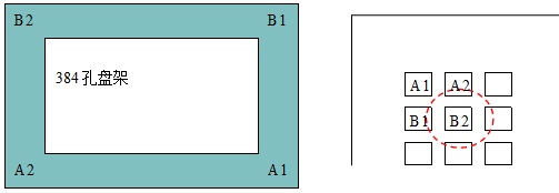
For example, pushing the 384-well plate to the upper left corner, the 96-tip is aligned with B2 and 96 holes in the same position, such as B4, D2, D4, etc.
First pipetting operation preparation
After booting up, each page already has default parameters, and you can run the default action directly to familiarize yourself with the device.
The sequence process is demonstrated by the program of 1 1 1 spray 100 ul displayed after power on:
Place the source solution tray and target tray on the work tray, and place the tip box on the tip and place it on the tray.
Click the "RUN" button on the touch screen interface. Press the operation button (2 button) on the operation handle to prepare for the aspiration.
It can be left and right, and the XY axis is pushed forward and backward for practice. You can press the up and down buttons (3, 4 buttons) to practice.
Press the operation button (2 button) on the operation handle again, and the action is 100ul.
Press the operation button (2 button) on the operation handle again, and the spray is 100ul.
Press the operation button (2 button) on the operation handle again to end this exercise.
Operation interface and basic operation of software
This chapter will introduce the software overview of the pipette and the handle operation to complete the first pipetting.
Operating handle introduction
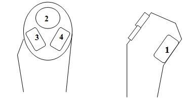
Front view of the handle Side view button 2: operation button, trigger the next piston action;
Button 3: Z-axis (pipetting head) moves downwards, including inserting the tip;
Button 4: Z axis (pipetting head) moves upwards;
Button 1: Function button, equivalent to Shift button, no function alone, combination function includes:
Shift + button 2: Trigger special action interface, including off tips, slow moving Z axis, see the following figure;
Shift + button 3: Quick positioning action, the liquid head quickly reaches the set height;
Shift + Button 4: Switches the set height.
When Shift + button 2 is pressed, a special action interface pops up:
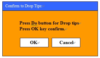
At this point, pressing the operation button or clicking the OK button on the screen will trigger the de-tips action. Remove the Tips baffle and move the attached tip down.
After taking off the Tips, the pipetting action will not be completed. Please be cautious.
Software introduction and basic operations
Automatically enter the first interface of the operating software after booting:
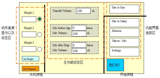
Height display and setting area: The height of the liquid processing head can be preset, which is convenient for quick key operation without having to observe the insertion position of the tip every time. Up to 3 heights can be set. The Shift + 3 key combination automatically advances to the set height, and the Shift + 3 key combination switches between the three set heights.
The simplest pipetting operation
Silicone Sex Doll,Adult Silicone Sex Doll,Silicone Sex Doll For Men,Full Size Silicone Sex Doll
Shenzhen Joyfun Sex Toys Co.,Ltd. , https://www.joyfunsextoys.com